Get the most out of your threading tools with our expert support resources. Explore detailed information on feed and speed recommendations, formulas for thread depth, and troubleshooting tips to optimize performance and extend tool life.
Threading Tools Technical Support
Feed and Speed Chart
| Material | HB/Rc | SFM: Uncoated | SFM: AlTiN+ | Tool Diameter .040-.050* | Tool Diameter .060-.092* | Tool Diameter .120-.152* | Tool Diameter .180-.232* | Tool Diameter .290-.362* | Tool Diameter .373+* |
|---|---|---|---|---|---|---|---|---|---|
| Cast Iron | 160 HB | 75-200 | 200-550 | 0.003 | 0.004 | 0.005 | 0.007 | 0.008 | 0.009 |
| Carbon Steel | 18 Rc | 75-200 | 200-450 | 0.003 | 0.005 | 0.006 | 0.007 | 0.008 | 0.009 |
| Alloy Steel | 20 Rc | 75-200 | 200-425 | 0.003 | 0.004 | 0.005 | 0.006 | 0.007 | 0.008 |
| Tool Steel | 25 Rc | 75-175 | 175-300 | 0.002 | 0.003 | 0.004 | 0.005 | 0.006 | 0.007 |
| 300 Stainless Steel | 150 HB | 75-175 | 175-350 | 0.003 | 0.003 | 0.004 | 0.005 | 0.006 | 0.007 |
| 400 Stainless Steel | 195 HB | 75-210 | 130-420 | 0.003 | 0.004 | 0.005 | 0.006 | 0.006 | 0.007 |
| High Temp Alloy (Nickel & Cobalt Base) | 20 Rc | 50-130 | 130-300 | 0.002 | 0.003 | 0.003 | 0.004 | 0.005 | 0.005 |
| Titanium | 25 Rc | 50-100 | 120-275 | 0.003 | 0.003 | 0.004 | 0.005 | 0.006 | 0.007 |
| Heat Treated Alloys (38-45 Rc) | 40 Rc | 50-100 | 100-200 | 0.002 | 0.002 | 0.003 | 0.004 | 0.004 | 0.005 |
| Aluminum | 100 HB | 75-250 | 250-750 | 0.004 | 0.005 | 0.007 | 0.008 | 0.010 | 0.011 |
| Brass, Zinc | 80 HB | 75-300 | 250-650 | 0.003 | 0.005 | 0.006 | 0.007 | 0.008 | 0.009 |
SFM = Surface Feet per Minute
Parameters are a starting point based on machinability rating at hardness listed. Check machinability rating of the material to be machined and adjust First Pass Depth.
*First Pass Depth
| Formula Name | |
|---|---|
| Pitch | 1 ÷ TPI (Threads per Inch) |
| Acme Thread Depth | Pitch x 0.5 |
| Stub Acme Thread Depth | Pitch x 0.3 |
| NPT Pipe Thread Depth | Pitch x 0.76 |
| Internal 60° Thread Depth | Pitch x 0.54 |
| Feed Rate | Pitch x Number of Thread Starts |
Thread Depth Formulas and Information
Minimum Depth per Pass should not be less than 0.0003.
Threads not ending in a relief need at least one thread pitch length of pullout.
Make sure the feed rate calculation does not exceed the maximum feed rate of the machine.
| Problem | Cause | Solution |
|---|---|---|
| Rapid Flank Wear | Cutting Conditions | Check for excessive feed and speed. See above chart for recommendations. |
| Tool | Select a coated tool. | |
| Part | Make sure prior operation did not work harden the metal. | |
| Built-up Edge | Tool | Select a coated tool. |
| Cutting Force | Increase the number of passes. | |
| Heat | Use an SCT coolant holder. If coolant is not available, use shop air and a coated tool. | |
| Corner Breakage | Cutting Conditions | Reduce the depth-of-cut on the first pass. |
| Program | If there is no thread relief, withdraw the tool on an angle. | |
| Part | End in thread relief. | |
| Chips Wrapping Around Tool | Tool | Use a tool that is at least 30% smaller than the hole diameter. |
Troubleshooting Common Problems
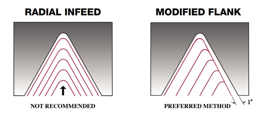
Radial Infeed is not recommended. Modified flank at 1° is recommended.
For unfavorable length-to-diameter ratios or difficult-to-machine materials, the number of passes will need to be increased up to 40% more.


